Dialing In My Frustrating Frustum

Yesterday I decided it would be fun to create a 3D model of a pyramidal frustum.  I have no idea how this popped into my head, but I've decided to blame it on my friend Mike P., from way back in junior high and high school.  Mike had a great knowledge of the esoteric and was quite a good artist.  It's quite possible that while we were playing Car Wars one day he made an offhand comment like, "If I designed a house it would be a pyramidal frustum."  That'd be just like Mike.

So yesterday I decided to model my own pyramidal frustum, and because no project can be left simple, I decided to embed Fibonacci spirals in the faces.  (Plus, anything with a Fibonacci spiral is automatically +5 in Mysterious, right?)  You can see the OpenSCAD code for the modeling if you like, but here I'm going to talk about dialing in the FlashForge Dreamer settings to make a nice print.

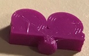
The four prints in the photo are ordered left to right from first printed to final print.  The first print's pretty bad.  The copper layers are really uneven and the edges are stringy. The blue spirals look terrible -- the second extruder leaked blue filament everywhere, yet somehow managed to not fill well in the print itself.  Go figure.  I'm using Simplify3D to slice and in that first print, the Hatchbox bronze PLA was set at 180 while the Metalink blue was set to 200.

(My Dreamer has upgraded nozzles which tend to make Hatchbox PLA print at lower temps than the original nozzles.  However, I just got this Metalink filament recently and used it to print all the sea tiles for a Settlers of Catan set quite nicely at 200C.)

For the second attempt I decided to turn on retraction and coast at end.  I was trying to avoid using a priming pillar because pillars really add to the length of a print.  I find that the priming pillar needs to be 10 or 12 mm square, minimum, to NOT break away from the print bed.  When your pyramid is 30mm square at the base, that priming pillar adds significantly to the overall print time.  So, retraction on to 2mm, coast at end of Simplify3D's default .2mm.  Result: a still very crappy looking frustum.

Third attempt: increased the retraction to 5mm and the coast at end to 2mm.  (Yeah, that's a big jump in the coast value.)  I also lowered the temp on my Metalink filament to 190, since it was still leaking little drops of blue all over the place.  The threading seems to have gotten even worse in this one.

Fourth try: all right, I'm turning on the ooze shield.  I use this feature a lot when I print dice, since it helps prevent cross-contamination of the filaments.  I'd been trying to avoid this since it adds to the print time; not quite as badly as the prime pillar, but noticeably.  In this case, the print time went from 36 minutes to almost exactly an hour.  Yikes. 

On the other hand, the ooze shield made that fourth frustum come out far nicer than any of the previous attempts.  I did leave my retraction and coast set the same as the third attempt, but the ooze shield clearly made the biggest difference.  I'll have to experiment further with tweaking the retraction, extra restart distance, and other related settings.  For now though, when someone has a critical need for a pyramidal frustum, I'll have to stick with the ooze shield.


Modular Printing to Avoid Support

I decided to model some custom pawns for Film Tycoons this weekend.  The "old fashioned" film camera might be the most iconic (non-copyrighted) symbol of American film, so it's the most obvious pawn choice.  It also has a very pleasing silhouette; you glance at it and know immediately what it is.  That outline structure causes some 3D printing issues, though -- there are a lot of unsupported overhangs at angles which can't be printed.

Quick lesson for those who aren't familiar with 3D printing: an unsupported section is any bit of plastic which does not have plastic directly beneath it.  Consumer grade 3D printers work by laying down layer after layer of plastic.  (The layers in these pawns are .2mm tall.)   The layers can gradually shift as the print builds; up to a 45 degree incline is quite safe and you can get even steeper if you print slowly.  Hence, the tripod legs will print with no problem.

Check out the front of the lens housing, though.  That's 90 degrees to the print bed and hanging in thin air, about a centimeter above the table.  Try to print that and you're going to end up with a big glob of plastic

One way to handle this is by printing support.  The slicer (the software which translates a 3D model file to code for the 3D printer) can add in columns of plastic with a more diffuse density and a weak connection to the layer being supported.  The support columns break off easily from the part.  However, supports increase the overall print time, they can leave rough spots on the surface of your model, and they can increase risk -- if the support doesn't have a wide base it can break away from the print bed and cause your print to fail just as easily as the finished part itself.

Instead of printing one solid part with support I decided to cut my model into three pieces, each of which could be printed with no support, then glue them together.  From the base to the connecting point on the tripod was one logical piece, the camera body and lens are another, then the reels. 

I hate gluing flat pieces together, though.  No one wants to hold two pieces together for ten minutes while the glue dries, right?  Especially if there are two gluing operations per pawn and I'm printing six pawns.  That's...a lot of time that I could be playing Ruzzle. 

The answer: pegs and holes.  (Ikea figured this out a long time ago, too.)  The camera housing has a hole on both top and bottom.  the tripod and reels each have a peg.  Besides making the gluing easier, this helps ensure that the pieces are aligned the correct way. 

I actually turned this 90 degrees to the left for printing, so that the lens pointed straight up.

I actually turned this 90 degrees to the left for printing, so that the lens pointed straight up.

I also use this little technique when slicing larger prints into pieces that will fit on the printer.  My Maltese Falcon is an example of that; I wanted it to be the same size as the movie prop, which meant slicing it into three parts.  Peg holes helped keep his parts flush at reassembly.  (Clarification: I didn't create this awesome Falcon model; I printed someone else's model from Thingiverse.)

A couple of other interesting production notes.  First, the to make the peg/hole arrangement really work well, the holes should be cylinders with different diameters at the ends.  In this example my pegs have a diameter of 4.5mm.  The holes have a diameter of 5mm at the opening and 4.6mm at the back, providing a snug pressure fit.  The pieces actually stay together pretty well without any glue.

Second, note the orientation of the housing -- I printed it with the back side flat against the print bed, lens pointing up in the air.  Why?  The peg holes have a 90 degree overhangs.  The one on the bottom could potentially sag during the print.  Probably not a big worry in this case because the widest of those "roofs" is only 4.6mm, but it's still a good practice.

Sometime soon I'll post the OpenSCAD file for this model either here in my site or on Thingiverse.

Dual Extruder Dice

Quick example (and test blog) demonstrating one of my favorite things about my FlashForge Dreamer: dual extrusion. 

A dual extrusion printer, as you've probably guessed, has two extruders.  This means you can run two filaments through the same print without having to pause the print and change the filament.  Consider these dice -- since the printer lays down plastic in .2mm layers, if I wanted to print the dice with a single extruder printer I'd have to pause on almost every single layer, change the filament, and resume printing. 

Personalized dice for a Reddit Gifts match.

Personalized dice for a Reddit Gifts match.

Keep in mind that a filament change means moving the extruder head away from the print, heating it up to 240 C, feeding the new filament while flushing the own, then lowering the temperature back to ~180 C before resuming the print.  That's a lot of time, a lot of unnecessary heating and cooling of the extruder nozzles, and a lot of wasted filament.

That's 75 filament changes.  Yikes.  There are a couple of ways you can minimize that pain or get around it.  First, if you had a bunch of dice to print you could produce ten or twenty at once; that would get you more print time for every filament swap.  (But still, 75 filament changes!)  You could also leave the pips or numbers as voids, either painting them in after printing or using a 3D pen to fill in the blanks. 

I do enough multi-filament printing that I'd much rather just have the dual extruder printer, of course.  And, as I'll show in a future blog, the dual extruder also provides solutions for some tricky printing scenarios.